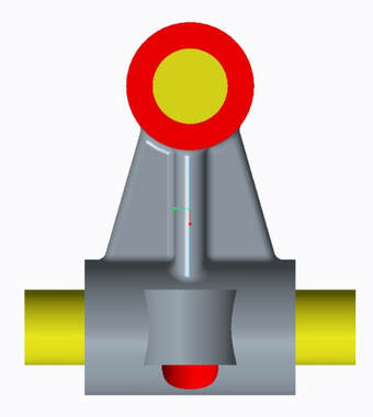
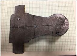
The objective of this project was to model and assess a complex piece of machining in order to locate its center of gravity and moment of inertia. These objectives were found experimentally and by using computer aided design software, creo, to compare the error of human experimentation versus the accuracy of a computing system. Driving dimensions in this project were measurements of the part taken by hand using a basic ruler and calipers and using symmetry to increase ease in finding centers of gravity.
Methods of Determining Center of Gravity
Plumb Line:
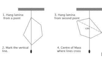
This method requires the irregular object to be hung from a string. A longer weighted string will also hang from the same point. The center of mass of the object will always fall along the path of the weighted string. In order to find the true center of mass, the line where the string falls is traced and the object is repeatedly hung from different points. Lines of where the longer plumb line hangs will intersect and its point of intersection is also where the center of mass is located. This method is relatively simple for a flat three dimensional object where the center of mass in one direction can easily be found halfway through the plane because it is of uniform width. But, for irregularly unflat three dimensional objects this method proves to be more difficult.
See Saw Method:
The objective of this method is to find balancing points of the object being measured by using a see-saw balance. For this method to work, the object is placed at one end of the see-saw and slid along the planar surface until the table is in balance. The object will theoretically come to rest with some portion of it resting on the midline of the plank being used as the see-saw. A line is then drawn on the object at the location where the object is on the midline. Now, from the other end of the seesaw the same procedure is done in a different orientation with a new line drawn here. Due to the object sliding from the other side of the table, the table will not come to balance with the object in the same position as it was on the other side. A line is then drawn where the object crosses the midline from the opposite side. Where these lines intersect is the center of mass. By rearranging the positioning of the object, lines can be seen as planes that will intersect and create a center of gravity in three dimensions.
Both methods were utilized in order to find the center of gravity, with both resulting in approximately the same location.
Methods of Determining Moments of Inertia
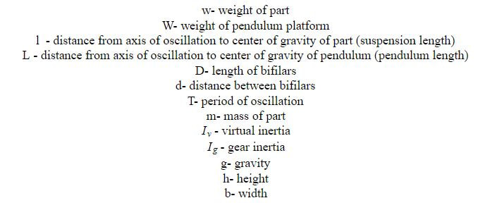
The following list of variables will be used throughout this section of the report to explain calculations completed in finding inertia:
To calculate the moment of inertia of the part, equations for compound pendulums were used to calculate inertia in the x and y direction and torsional equations were used to calculate the z component. The equations used were provided from the National Advisory Committee for Aeronautics (NACA).
Tests had to be performed prior to the calculations in order to correctly use the variables given. The first tests done were for the compound pendulum. The equations used to solve for the inertia in the x and y direction were listed below. Values that were listed in the equation for determining the true mass of an airplane and correcting for its shell like structure were ignored, as the object being tested was a solid body.
Tests had to be performed prior to the calculations in order to correctly use the variables given. The first tests done were for the compound pendulum. The equations used to solve for the inertia in the x and y direction were listed below. Values that were listed in the equation for determining the true mass of an airplane and correcting for its shell like structure were ignored, as the object being tested was a solid body.
After doing some correcting to the NACA equation, the final equation below was used to calculate for compound pendulums.
Experimental Pendulum Tests
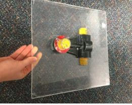
To calculate an experimental value for inertia, a standard pendulum test was run on the part. The first test runs were for the compound pendulum, solving inertia in the x and y direction. The goal behind this experiment was to find the period of the swinging part at two different heights per orientation. Theoretically, at two different heights the difference in period would correct for the difference in distance to the center of gravity from the points of oscillation. The plate was suspended from a measuring sticking bridging the gap of two tables with fishing wire, supporting two ends of the plate. The center of gravity was marked on the plate and the center of gravity of the part was placed in the same location with the part oriented for either x or y testing. The part was pulled slightly back and released, while simultaneously a timer was running and using the “lap” function, the amount of time taken for one oscillation to complete was recorded. This process of multiple oscillations was repeated for the x and y directions. Length and mass of the plate were also recorded.
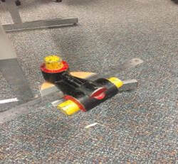
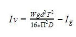
To calculate inertia in the z direction, a torsion test was used. To do this, a small cardboard circle was cut out and fishing line was attached two two ends opposite one another via paperclips. The part was then placed with its center of mass coincident to the center of mass of the circle. Without creating any horizontal swinging, the part was rotated in a clockwise direction and released. Similar to the compound pendulum tests, the part completed ten periods, five times which were recorded and the average of each test was found.
Due to the lightness of the cardboard, it was unable to support the full mass of the part. Both the part and plate had their center of masses in the same place, but, because the cardboard was so light, it could not mechanically support the load of the part. In order to correct for the lack of support, a metal ruler was placed across the circle, crossing through its center, with the part then resting on top of the ruler. The addition of the ruler helped to distribute the weight of the part in a more balanced and sturdy manner. A trial at a second height was done in order to compare values and reiterate the accuracy of the experiment. The equation used to calculate torsion in the z direction can be seen below.
Due to the lightness of the cardboard, it was unable to support the full mass of the part. Both the part and plate had their center of masses in the same place, but, because the cardboard was so light, it could not mechanically support the load of the part. In order to correct for the lack of support, a metal ruler was placed across the circle, crossing through its center, with the part then resting on top of the ruler. The addition of the ruler helped to distribute the weight of the part in a more balanced and sturdy manner. A trial at a second height was done in order to compare values and reiterate the accuracy of the experiment. The equation used to calculate torsion in the z direction can be seen below.
Creo Enbaled Calculations
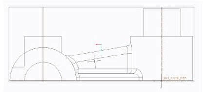
The solid body used for tests was created in creo and had its center of gravity found. The dimensions of the 3D part were measured and used to recreate an identical model. The part was modeled using the material steel, also the material the part was made of. The entire part was made of one material causing for uniform density and material having no effect on the locations of center of gravity, but affecting moment of inertia. To find values in Creo, a mass properties analysis was used.
To compare results, the distance found experimentally from the center of the extruded circle to the experimental center of gravity in the x,y, and z direction were found and compared to the computer output. The ruler used to find all measurements in the project had a margin of error of 1/16” as that was the smallest measurement that could be calculated. The part was symmetrical about the x plane, resulting in no deviation on either side of the y plane that intersected it. In the x direction, the point where the x and y experimental lines intersected was the same distance from the csys as on the computer. To experimentally find the z component of the center of gravity, the plumb line approach was used. A string was attached to the peak of the originally extruded circle and the part was hung from the edge of a table. Due to the irregular shape, the straight line edge of the table leg that was perpendicular to where the part was hung from was used instead of a plumb line. Using a plumb line, the line kept touching the hanging part and getting stuck on its unusually shaped surfaces. In order to use a horizontal line without having to have a collision, the straight leg was used instead, but, there was a 0.10 inch difference between the experimental z value found and the computed value.
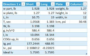
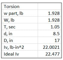
Upon completing all calculations in an excel file, the values found were compared to those calculated by the Creo Program. Overall, inertia with respect to z was very similar to the desired value, varying by 0.47 psi. Satisfied with values found for torsion, values for inertia in the x and y direction proved to be far less accurate.
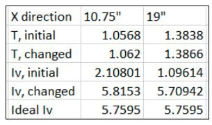
By changing the periods by hundredths of inches, inertias were obtained that matched those of creo. In the table showing inertia in the x direction, it can be seen that by changing the period by hundredths or even thousandths of inches, the inertia may effectively increase by more than double the original amount.
Conclusions
Once data had been analyzed from the lab and compared to outputs from creo, it was thought that the experiment or calculations had a significant amount of user error in them. But, it was realized that the methods used to calculate inertia proved to be accurate, but, the precision and accuracy needed to correctly measure period by hand relied heavily on luck and ability to hit the timer at the exact moment the oscillation completed. As seen above, measurements to the thousandths of seconds were critical, a standard that is hard to meet when human error is put in the equation. After small adjustments, inertia found experimentally and by creo were found to be similar to one another.
