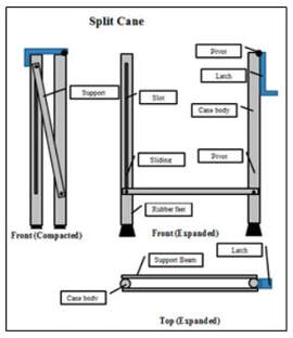
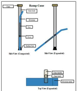
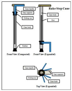
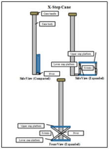
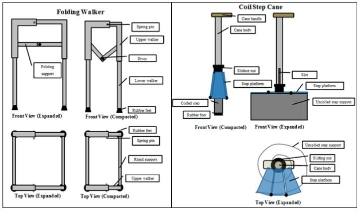
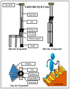
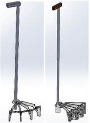
Climbing stairs or steps is a common daily activity. However, stairs can be a fatal activity for those that are unable to properly make an ascent or descent. Of all the deaths that occur from falls per year, 10% occur from falling on stairs, making it the largest category for fatality in the act of falling (Startzell, 2000). The initial goal of the project was to create a cane design with a retractable, foldable, and/or adjustable step, to increase the ability of the elderly to traverse stairs and steps.
Design Iterations
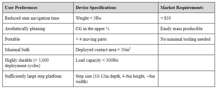
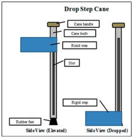
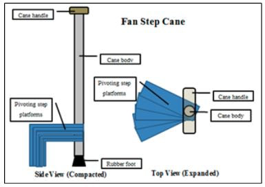
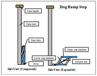
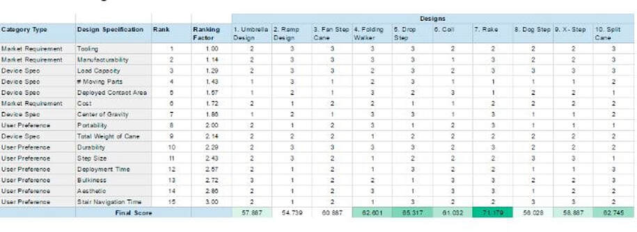
In order to complete this project, a group of four was assembled with the task of creating a device that could aid in daily living activities. A broad subject, we brainstormed several ideas and decided that our goal would be to create a cane that would aid in traversing stairs. Once we had settled upon this idea, a variety of design iterations were made. Each design was then rated on a scale of 1-3 related to how well it met each design criteria. In this scale, a 3 indicates that the design performed exceptionally in this area, a 2 indicates that it performed adequately, and a 1 indicates that it performed poorly. These rankings are quantified for each design criteria as follows.
The final design with the highest score was the drop step design. My "position" in the group was Chief of Information. The other three positions were Chief of Manufacture/Finance, Design, and Executive Officer. As CIO, my role required the research into various fields such as target audience, functional limitations, gait comparisons, environmental and architectural constraints, current solutions on the market, and so on. Having the knowledge background, I was able to provide educated suggestions on components of design and materials choices.
Developing a Target Audience
In order to design an assistive device that met consumer needs, we interviewed a local target audience by visiting the Easter Seals and Worcester Senior Center. From the user input and background research, the team identified that the main target as those that have limited range of motion and strength in the lower limbs. People that fall into this group include those that:
- Received their first assistive mobility device (voluntarily or by doctor recommendation)
- Have some lower limb surgery or recently had a lower limb surgery (Knee, Hip, Foot)
- Are ages 70-80
- Are under the average step number for the 2-minute step test
Revised Goal
Upon conducting more extensive background research and doing some initial client surveys the team revised the goal of the project to be product inclusive. The revised goal is to create an aesthetically pleasing assistive device that can be used to traverse stairs in an efficient and useful manner. This goal did not limit the project to designing a cane as a step cane may not be the best solution.
Prototype Design, Analysis, and Construction
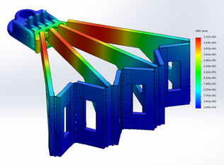
A total of four stress cases were tested: best case, worst case, and two immediate cases. In the best case scenario the 350lb load is applied in the vertical direction across the surface of all four L-pieces and all the linkages. The bottoms of these pieces and the sliding shuttle are fixed. The results of this analysis show that the von Mises stress are well below the yield stress for both ABS and acrylic, stresses are all below 15 MPa. The maximum stress, 89 MPa, is on the bottom of the hinges, but this is well below the limit for stainless steel. The image below shows best case displacement.
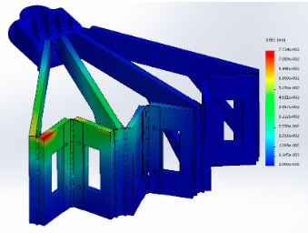
In the worst case, the 350lbs is applied just to two of the linkages, in this case the left two were chosen. This situation would result if the user stepped on the device from the wrong direction. For the L-Pieces and linkages, the stresses are all below 50 MPa. While the stress has increased on the hinges, the average value is around 82 MPa which is well below the limit for stainless steel. However, in this scenario the bottoms of the hinges experience of stress concentration of 196 MPa which while below the limit for stainless steel indicates that this situation should be avoided if possible by providing good instructions for the device. When testing the displacement of the worst case scenario, the greatest amount of displacement that occurred was less than one tenth of a millimeter.
Prototype Movements
Gait Analysis:
The design functions identically to the step canes on the market today, such as the EZ-Step. This gait pattern reduces the required range of motion for the user and the target audience that has reduced range of motion already. Although in our background research, a step-over-step design is desirable in rehabilitation due to the decrease travel time and strength building, this process is not possible with a step cane. Instead the focus on the design was to make the step more compact, less bulky, and fix the moment of inertia problems with a traditional step cane/quad cane. These improvements to the step cane will make it more desirable than existing products and hopefully improve the time to traverse stairs.
Vertical Sliding:
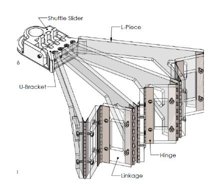
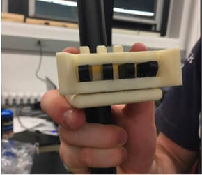
The main component that will hold all of of the L-pieces together will be the 3D printed u-bracket attached to a 3D printed shuttle slider. The slider has an inner diameter that is slightly larger than the cane’s outer diameter shaft to allow for ease of sliding. The slider also has 4 main grooves that allow the bracket holding the 4 L-pieces together to fit on the slider. The slider and the L-piece bracket have a center hole drilled through them to allow for a pin to connect the pieces and function as a hinge joint.
Rotation of Rake:
The shuttle slider and the u-bracket connecting all 4 L-pieces and are pinned together to function as a hinge joint. The shuttle slider was designed to have stoppers on the hinge joint to only allow for 90 degrees of motion for the L-pieces. This limitation prevents the L- pieces from over extending and clanking against the cane or creating a difficult step angle when in the rake position.
Additionally, the slider has an X-shaped groove at its bottom to securely lock in place when in its rake position, see Figure 4. The reasoning behind the X-shaped groove is so that a bolt can be drilled through the bottom of the cane shaft and stop the shuttle slider from moving farther down. The X-shape also offers the user to rotate the step in 90 degree increments so that the step can be adjusted for a right hand or left hand user, or the step can be rotated out in front or behind the cane to function as a quad cane if needed.
Expansion/ Compression of L-Pieces:
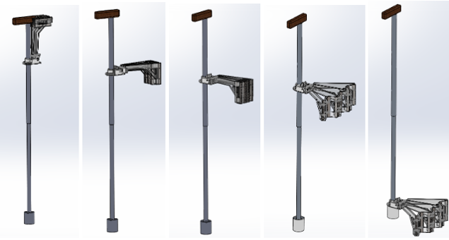
Parallel position means the L-pieces are compressed parallel to each other and are locked in the parallel position with the longer side of the L-pieces parallel with the cane in the zero degree position. The rake position is when the L-pieces are expanded to form a rake and when the slider is locked into place at the bottom of the shaft of the cane; ready to be stepped on.
Fixed Parallel Position:
A velcro strap secured on the cane will be used to firmly secure that the L-pieces are in parallel position with the shaft. The velcro strap will prevent pieces from unexpectedly unfolding while walking with the cane. Additionally the strap is an intuitive and simple design. A fabric strap with a buckle is looped around all of the L-pieces to compact the L-pieces. The user simply pulls on the strap to tighten it and releases the buckle to expand the rake. The reasoning behind using 2 straps was so that the user may operate each one at a time only using one hand so that the other hand is securely holding the cane at the handle.
Fixed Rake Position:
The L-pieces are “spring” loaded with foam wedges taped between the L-pieces. When the strap buckle is released, the rake automatically expands due to the expansion of the foam. The foam is strong enough to expand the rake but also weak enough so that the user can easily compact the rake. Expansion of the rake is limited in two ways: the u-bracket contains “wings” that center the rake and a fabric covering is velcroed to the tops of the L-pieces. These features keep the rake centered and only allow to expand so that the linkages are perpendicular.
Deployment Sequence:
Materials
The main components include the sliding shuttle and U-bracket, which was 3D printed out of ABS and used to attach the acrylic L-brackets to an aluminum cane.The linkages were also made out of acrylic. Foam naturally expands and was placed in between each L bracket to keep the rake in its expanded state. Polyester fabric was used as a covering over the the top surface. Steel hardware was used for all the nuts, screws, and bolts.
Final Product
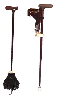
Once the analysis was complete the team constructed the prototype using a mixture of custom fabricated and off the shelf parts. A standard derby style cane was purchased to serve as the foundation of the device. The shuttle slider and u-bracket were 3D printed on the Dimension SST 1200es printer, in the WPI Design Studio, out of ABS plastic. The L-pieces and linkages were laser cut using the Versalaser VLS-4.60 laser cutter in Washburn Shops at WPI. With all of these major parts manufactured, they were assembled with standard nuts and bolts. Some modifications to the parts were made using files, drills, and hack saws. With the rigid components assembled the team attached the foam wedges with duct tape and then cut a custom fabric covering and attached it to the L-pieces using velcro.
While constructing the rake design prototype the team started doing some kinematic stress tests before actually testing the prototype with a physical step. The first test conducted was releasing the cane from its collapsed version where the L-pieces were vertically in line with the cane and rotating out 90 degrees so that they would become parallel with the ground. The weight of the device and the free swinging nature generated a large moment causing the L-pieces to snap near the connections to the bracket. The team was able to clamp the step portion back onto the sliding collar using scrap pieces of acrylic, nuts, and bolts. As a result, the device lost its capacity to expand into the appropriate size step and was deemed unsafe for human use. A redesign of how the L-pieces are connected to the bracket or a redesign of the bracket itself would be required for a second order prototype.
While constructing the rake design prototype the team started doing some kinematic stress tests before actually testing the prototype with a physical step. The first test conducted was releasing the cane from its collapsed version where the L-pieces were vertically in line with the cane and rotating out 90 degrees so that they would become parallel with the ground. The weight of the device and the free swinging nature generated a large moment causing the L-pieces to snap near the connections to the bracket. The team was able to clamp the step portion back onto the sliding collar using scrap pieces of acrylic, nuts, and bolts. As a result, the device lost its capacity to expand into the appropriate size step and was deemed unsafe for human use. A redesign of how the L-pieces are connected to the bracket or a redesign of the bracket itself would be required for a second order prototype.
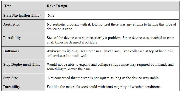
Professor Cobb is an individual who is in his late 60s with limited range of motion in both his left arm and leg due to hemiparesis. Although Professor Cobb is under the target audience in terms of age, his usage of a cane regularly, limited range of motion, and availability to test the device qualified him. Below are the responses Professor Cobb had to particular user preference metrics in a one on one interview.
Conclusion
By examining the medical and social problems associated with stair and step navigation in the elderly it is clear there is a need for an improved product. The elderly are at high risk of falling on stairs and steps and those falls are more likely to be fatal. Current products to address this problem are either too expensive, limit the user to indoor environments, or are too bulky. Therefore, the team sought to perform a user need and function analysis of the elderly in Worcester and develop a mobility assistant to improve their ability to navigate stairs and steps. The final product would be competitively priced and sized to existing canes or walkers. Such a design would capitalize on the growing mobility assistance market and improve the health and well-being of the elderly.
The final design created met the goal the team had set for the project. A device was created that was more aesthetically pleasing than what was already on the market and could be used to aid in traversing stairs both in the home and also in public. Overall, the design that was made was assumed to be safe for use. However, when initially testing the design, it can be seen through the failure of a part that it did not accommodate for the forces of rapid acceleration and abrupt deceleration. Although the design was flawed, it was decided that this overall design was a first order prototype that with revisions that there was not enough time for in the seven week term could lead to a competitive walking aid. While there are slight modifications that needed to be made such as material used to prevent part failure along with a redesign of the U-bracket, the overall concept of the device remains wholly the same.
The final design created met the goal the team had set for the project. A device was created that was more aesthetically pleasing than what was already on the market and could be used to aid in traversing stairs both in the home and also in public. Overall, the design that was made was assumed to be safe for use. However, when initially testing the design, it can be seen through the failure of a part that it did not accommodate for the forces of rapid acceleration and abrupt deceleration. Although the design was flawed, it was decided that this overall design was a first order prototype that with revisions that there was not enough time for in the seven week term could lead to a competitive walking aid. While there are slight modifications that needed to be made such as material used to prevent part failure along with a redesign of the U-bracket, the overall concept of the device remains wholly the same.
