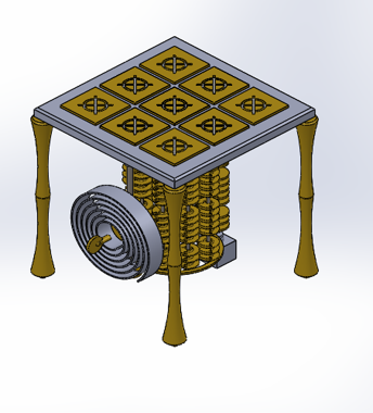
Final Design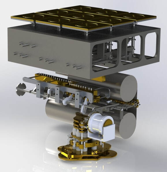 The Major Qualifying Project (MQP) was completed in a group of four students during senior year. The objective of our project was to design, test, and build a mechanical tic tac toe machine. 3 parameters were set at the start of the project:
Prototypes
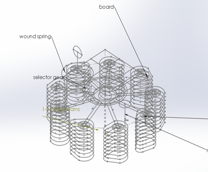
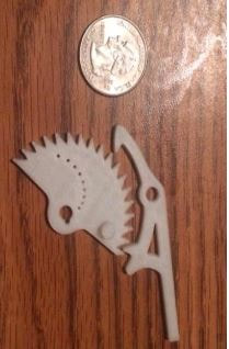
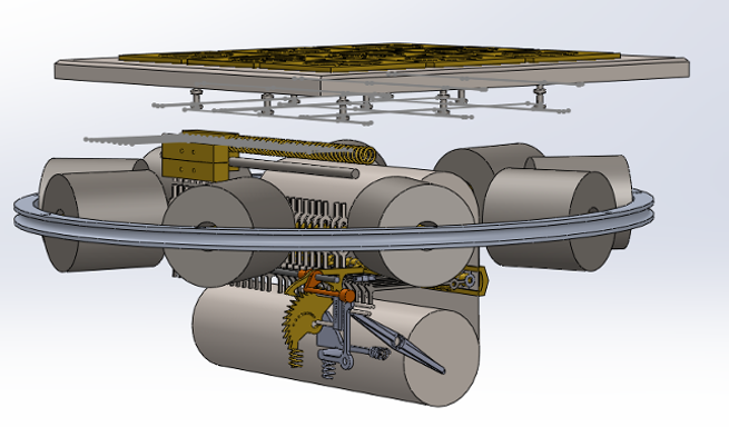
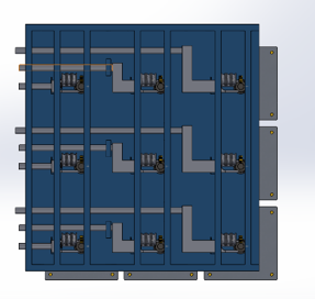
A key take away in earlier iterations was the escapement mechanism. Escapements are often found in mechanical clocks but have proven to be a key part in our machine. The escapement in our machine acts as an indexer for the gearbox. It allows the gearbox to know when the gear makes one full rotation. The escapement for this purpose is being used as a mechanical counter that aids in the release mechanism process. If the player selects square 3 for example, the escapement comes around and hits the star wheel which lifts it, allowing for the escapement to advance one tooth forward. During this process, there are other star wheels being triggered by tines across the way but, during the first round only a set of two of these pins actually transmit any load higher than the transmission block that is located above the tines. So the tine comes up, locks, then the next come up, causing for the previous tine to unlock and release while the newly raised one locks, and this process continues. When the tines raise, lock, and unlock, the counter reaches 3, slides forward, locks, and the escapement moves forward slightly a click and that releases a clutch which goes into the main drive. With that released, that basically signals that the player stops cranking the input crank. Then the player knows to begin cranking the output. How It WorksStep 1: Choosing a Spool The user manually inserts the first spool and rotates it into position to allow for interfacing of the stored data with the machine. Step 2: Pick a Tile to Push The user pushes down on the tile as far as it can move. This vertical distance is 0.51 inches and the tile (B) is held down by a detent (A). To signify that the machine has selected a tile, the tile is pulled down .30 inches. Since there is such a small difference between these two, the tile is made of two different types of metal. When the aluminum is visible, it signifies that the user has played that tile. If only brass is visible, the machine has played that tile. 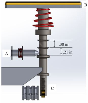 Step 3: Clutch Release The motion of the button being pushed down 0.51 inches transfers the linear motion into rotational motion via the rack and pinion (C). This is visible on the bottom of the tile shaft. This rotation creates tension in the cables. These cables are run down the side of the machine and connect to the 9 clutches in the indexing mechanism. When one tile is pushed, tension is created in one cable which releases one of the 9 clutches. This motion can be seen below. 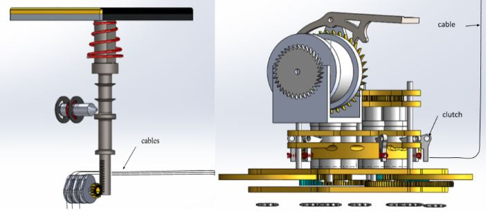 Step 4: Engage Escapement Once the indexing mechanism has rotated to the appropriate point, the escapement mechanism will allow the shaft connected to the gears to move. There are 9 clutches on the indexer and as mentioned above, only one is engaged at a time depending on which button the user pushes. Each of the 9 springs are in compression until the user pushes 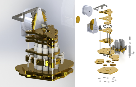 a button which causes tension in the cable attached to the clutch. The live shaft gear has 96 teeth along with 9 idling gears each having 12 teeth. Gear ratios vary from 1:1 through 9:1. Step 5: Turn Punch Card Wheel The user turns the crank which is attached to the physical library. As the crank turns so does the physical library (A in figure below). While there are nine available spools, only one is engaged at a time. 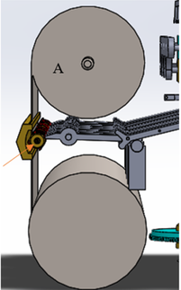 Step 6: Physical Library is Read Seen above, along with the physical library, is the star wheel and tine assembly. The holes in the physical library interface with the star wheels (B). As the star wheels are spun by the physical library, they interface with the tines in a similar manner a music box uses to create music. Step 7: Tines Move with Punch Card When the end of each tine is moved by the star wheel, it causes the other end of the tine to move upwards. In the process of moving upward, the tine hits a hinged plate. The plate moves upwards enough that the tine resting on it falls downward. The tine that is still moving upward then comes down to rest upon the plate. The constant reading of holes on the punch card causes different tines to interact with the hinge plate, resetting the tine currently moved up with every new tine that interfaces with the computer. The y-shaped joint that is outlined in red was put in place to restrict the vertical motion of the left side of the tine. In order to interface with the next section of the machine, it only needs to move 0.5 inches. Additional vertical motion would be problematic in the next step. 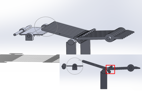 Step 8: Motion Transfer The tines mentioned above rise and the rear half interfaces with a set of pins that have a vertical movement associated with them. When each pin moves upward, it hits a lever which slides a cam into place. The camshaft then rotates which translates the motion from the tine blocks into horizontal motion in the wedges. 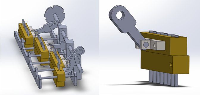 Step 9: Machine Selects a Tile Pictured is the wedge that was mentioned in Step 7. Each wedge moves 0.75 inches horizontally. This motion creates 0.2 inches of vertical motion downward for the tile due to the tapered shape of the wedge. When a wedge is moved horizontally, the associated tile is pulled down 0.2 inches. The image below shows all nine wedges interfacing with their respective tiles. The wedge is spring loaded, allowing for easy reset once a new tile is played.
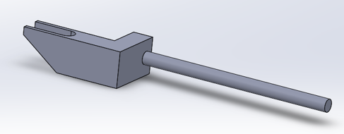
Tine Resets: The tines have a wedge block on the end of them that acts like a pendulum. As a tine swings up it moves the wedge back until the tine can clear it. When the tine clears the wedge block, the pendulum motion swings the block back to its starting position and the tine falls and rests on top of the wedge. When another tine swings up, the old tine falls as the new one moves the wedge and comes to rest on top. A simple, single position camshaft is used to swing the pendulums and reset the tines at the end of each game. Gearbox Reset: The gearbox has a clutch reset that encompasses all of the clutches. The plate is pulled upward and disengages all of the clutches in the process. These clutches need to be reset between each round of the game in order to clear old inputs and put machine on track to read the next set of plays on the physical memory Tile Reset: Each of the tiles is held down with a detent. All of the detents are spring loaded forward and attached to a bar in the back. After the game, the user would simply need to pull the bar back allowing the spring loaded tiles to return to their initial positions. Numerical System of Data In order to create a series of logical inputs and outputs i.e. physical memory, that the machine would be capable of reading, a game of tic-tac-toe needed to be represented in a matrix format. Changing the “X” and “O” inputs and outputs to be numbers based off of location on a grid allows for a better mapping of potential moves. Tic-tac-toe is a solved game. Our machine plays a defensive game which means it makes the second move. It is much harder to win a game of tic-tac-toe when going second. Our team analyzed each possible game and recorded the best strategic response for the machine to make in every possible scenario. To make coding our document easier, we assigned each of the nine spaces a number, one being the top left corner and nine being the bottom right, with values increasing across each row. 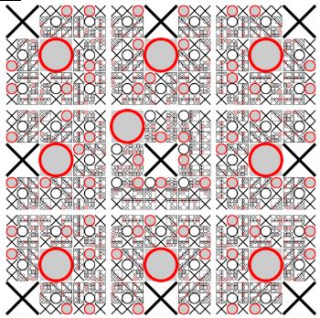 Our team used the defensive model found to the right to determine the best strategic output for our machine to produce in each situation. To demonstrate how our team used the data, we have broken down how our excel document can be used into each individual move. The example will outline a game in which the user selects tile 1 as their first move, tile 4 for their second move, tile 3 for their third move, and 8 for their final move. The user’s tile choice and the computer's response to that choice are called a “layer” in this document. For example, the user’s first move and the computer's response to that are called the “1st Layer” in this document. The “X” represents the user and the “O” represents the computer. The First Move: The user can play any of the nine options on their first turn. Strategically, the best spot to play is the middle tile (tile 5). If the user plays anywhere besides tile 5, our computer will respond by playing tile 5. If the user chooses tile 5, the computer responds by playing tile 1. The top row in the figure below outlines the possible places that the user could play. The second row contains the best strategic response for each possible input. For example, if the user played tile 1 (highlighted in yellow) the computer would respond by playing tile 5 (highlighted in green). 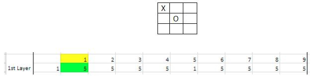 The Second Move: As the game continues, the responses become more complex. To keep track of the computer’s response, each row is labeled. The column second from the left contains each rows label. Row 1.1 denotes the situation in which the user played tile 1 on their first move. Row 1.2 denotes the situation in which the user played tile 2 on their first move. 1.3 is when the user played tile 3 and so on and so forth. Continuing with the example above, the user played tile 1 on their first move so focus on row 1.1. Tile 1 and tile 5 have already been played and therefore cannot be played again in the second layer so those values are blacked out in the figure below. Continuing with the previous example, the user played tile 4 on their second move and the computer responded by playing 7. This is shown below with the user’s move highlighted in yellow and the response in green. 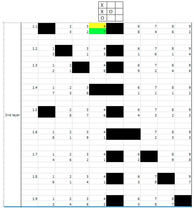 The Third Move: The row’s labels have grown by one number. For example, 1.1.2 user’s first move was tile 1 and his second was tile 2. As you can see below, row 1.1.1 is blacked out. This is because it is not possible to play tile 1 twice. Continuing with the example, the user has played 1 and 4 and the computer has responded by playing 5 and 7 respectively. As you can see in row 1.1.4, these four tiles are blacked out because the tiles are now out of play. For the purpose of continuing the example, the user’s third move is tile 3 (highlighted in yellow) and the computer’s response is tile 2 (highlighted in green). The figure below only shows 1/9th of the 3rd layer. Rows 1.2.1 through 1.9.9 are omitted for simplicity's sake. 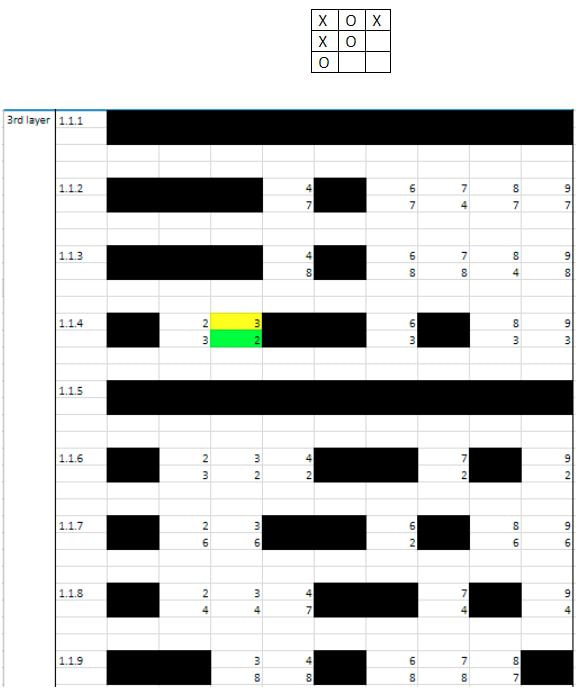 The Fourth Move: The figure below only shows 1/81st of the 4th layer for simplicity's sake. Continuing with the example, tiles 1-5 and tile 7 have been played. Therefore, only tile 6, 8, and 9 are visible in row 1.1.4.3. The user plays tile 8 so the computer responds by playing tile 6. The board now looks as follow:  The user could play a fifth tile; however, it would not change the outcome of the game. The result is a draw. 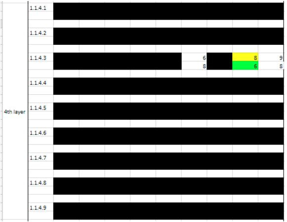 Binary Format of Data Compilation The original system that we created to keep track of data was a digital system. However, the punch card design runs on a binary system. The digital system allowed us to know what the proper response for the machine was but needed to be converted into a binary system so the the data could then be converted into cartesian coordinates and input into SolidWorks. Is there a hole or isn’t there? The data outlined in the previous section had to be changed from a digital format into a binary one. To achieve this, we created a series of excel documents. There are 9 excel documents, one for each of the tiles that the user can select as his first move. An example of this document is shown below. 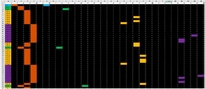 This image shows a section of the binary solution to a defensive game of tic-tac-toe if the user’s first move is to engage the top leftmost tile. The blue indicates the machine’s response to the user’s first move, the green to the second, yellow to the third, and purple to the fourth. The leftmost column indicates what section of the game is being referred to. For example, 1.1.3.8_9 has a 1 in column 6. That means that the user’s first move was to play tile 1, their second was tile 3, third was tile 8, fourth was tile 9, and the best strategic response to their fourth move is tile 6. This binary data was more useful than the digital data, however it still needed to be altered to fit onto a punch card. To achieve this, the team used excel to change each box in the excel into a data point on a cartesian plane. The space between each cell in the x direction is .28 inches and .25 inches in the y. The cartesian coordinates were uploaded into solidworks and used to create a CAD model of each of the 9 punch cards. Machining and Assembly The majority of parts used in the final assembly were built in the machine shops of Higgins and Washburn shops on WPI’s campus. Other parts that could not be made at WPI were outsourced to a contact at Massachusetts Institute of Technology (MIT) as a means to have parts cut with a water jet. Other standard parts (screws, etc.) and stock were ordered through McMaster Carr. In total, approximately 700 parts were used in the making of the computer, 500 of which were made in WPI facilities. The materials used to manufacture parts was primarily brass, aluminum, and 4140 steel. Manual Machining: A majority of the parts that make up our tic-tac-toe board were manufactured manually in the Higgins machine shop. Many of the parts we designed had only one or two copies needed for the construction of the board therefore, it was quicker to manually machine these parts than taking the time to write the program for the Computer Numerical Control (CNC) machining. The vertical mills in the Higgins shop were utilized for machining most of the parts that were made for the board. All of the rods that needed to be turned on a lathe were made using the manual lathe in the Higgins shop. All of the gears in our board were cut manual in Higgins using an Ellis dividing head. The dividing head allows the machinist to look up in a chart the amount of rotations needed to cut the correct number of teeth in a gear as well as the correct plate. The teeth of the gears were first cut using the horizontal mill and then parted off using the lathe. Computer Numerical Control Machining: The Computer-Numerical Control (CNC) machining was done using the Mini Mill and ST-10 (lathe). The allure of using CNC for machining is mass production and repeatability. For this reason, parts requiring high volumes were CNC machined. As there are nine tiles in a game of tic-tac-toe, there were at minimum usually nine parts of any given feature needed that interfaced with the tiles. For this reason, it was quicker to take a drawing for a part out of the SolidWorks file for the project and import it to Esprit, a computer aided machining (CAM) software. Once in Esprit, the part needed to be programmed once to be cut and the same program could be repeated on multiple parts with the only down time in between machining being entering new parts and re-probing surfaces. Esprit allows for a complete simulation of the part to be machined, a useful tactic to avoid potential collisions and a chance to review that all of the programming was inputted correctly. Feeds and speeds do not need to be manually entered into the machine during use, merely included in the program being created for the machining process beforehand. Mini Mill: The Mini Mill was used to machine parts that involved engraving, horizontal cuts, vertical cuts, or drilling and tapping. All of these functions were performed with the part being placed in a stationary constraint that allowed for no movement of the part. Some of the parts machined using the Mini Mill included the tiles that the user interfaced with. As seen, the engraved “X” and “O” features would not be a quick or efficient process to manually perform. As an example of precision, another feature that was created on the Mini Mill was the hydraulic block. The process involved milling out the base for all of the piston holes followed by the milling and reaming of each individual hole. 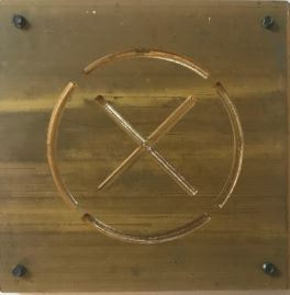 ST-10: The ST-10 Lathe was crucial for cutting patterns into a part that had radial cuts. The manual lathe proved to be very efficient in making parts that required basic turning down, drilling, or tapping. The use of CAM and CNC to make some parts on a lathe were reserved for those that could not be done on a manual lathe as the tolerances on the ST-10 proved to be slightly off compared to turning parts manually. Parts turned included the spring tab. 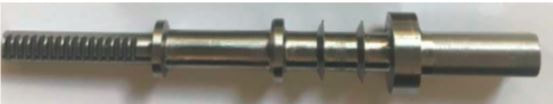 This part was turned on the CNC lathe and the rack that interfaces with the pinion was manually added along with turning down the section that the rack went on after the part had been turned and parted. Due to the length of this part and the diameter being cut, it was necessary to have a section of the part turned and tapped with a center drill in order to insert the tailstock. Once the tailstock was inserted, the roughing, grooving, and contouring passes were done up to the final wide diameter cap before the rack. At this point, the spring tab was parted and the final roughing was done in a manual lathe with the previously turned section being held in order to avoid the chatter and tolerancing errors of a long, narrow part being machined. Another part done on the ST-10 was the sprocket gear. The general disc shape was created using a CNC lathe. Once the disc was made and parted, it was placed in a fixture in the Mini Mill and the gear teeth were milled. Assembly: The complete design consists of several sub assemblies. In order to begin assembly of the machine, different subassemblies were first put together. During the process of assembly, parts were tested to make sure that the interfaces were efficient. Ultimately, the computer was not fully assembled. Sub assemblies were completed, but both time and budget caused for the project to be incomplete. Most sub assemblies were put together using methods such as inserting screws, set screws, bolts, hand peening, and press fitting. Loctite and other adhesives were also used in ensuring that parts would remain in the right spots and not shear. Further details of how this process could be improved were documented in our final paper for the project, but, for the sake of length here I'll keep it short. Constraints included: time, scrap parts and their incurred costs, designing for manufacturability taking more time than a normal 3D model, and shear. Most sub assemblies worked on their own, but, the accrued torques and stresses of the full weight of the machine caused for shearing. 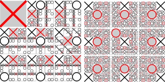
2 Comments
|
 RSS Feed
